
Modern industrial sites in Pune rely on organized systems to handle power effectively. A robust cable management strategy is essential for protecting wires in busy manufacturing plants. This ensures everything stays in order during daily operations.
Proper installation helps factories stay safe and run without interruptions. Using a high-quality cable tray ensures that your electrical lines remain accessible for regular maintenance. It also helps in preventing accidental damage to the wiring.
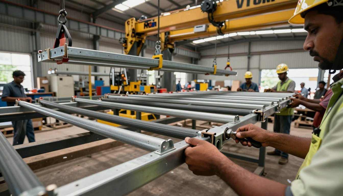
VTOM Cranes provides expert solutions for trays used in heavy-duty EOT crane environments. We focus on durability and efficiency to help your business grow. Our team handles projects that require specific technical standards.
This guide covers everything about a secure cable setup. Learn how a professional tray layout can reduce costs and boost system life. We aim to help you build a scalable and safe electrical network.
Key Takeaways
- Pune industries require efficient cable organization for safety.
- Professional setups significantly reduce operational downtime.
- Proper routing helps maintain high electrical safety standards.
- VTOM Cranes offers tailored solutions for industrial crane systems.
- Systematic layouts make future maintenance tasks much easier.
- Quality materials extend the total lifespan of electrical gear.
Understanding Trailing Tray Fitting Systems

Effective cable management starts with understanding the core components of trailing tray fitting systems. These specialized structures organize every electrical cable in a modern industrial facility. This infrastructure provides physical support while allowing easy access for future maintenance or system upgrades.
These systems enhance flexibility by helping cables navigate complex building layouts. High-quality fittings allow the path to change direction vertically or horizontally without damaging the wires. A well-planned tray layout accommodates multiple routes within one integrated framework.
- Mechanical Support: The system bears the weight of heavy cables to prevent sagging and physical stress.
- Environmental Protection: It shields sensitive wires from external hazards and mechanical impact.
- Heat Dissipation: Organized spacing facilitates airflow to prevent overheating in high-load applications.
- Enhanced Safety: The system maintains proper separation between different voltage classes and ensures grounding continuity.
- Stability: Proper installation distributes weight evenly across all sections to minimize strain.
A reliable setup uses specific components to ensure long-term durability. Engineers must choose the right accessories to maintain grounding continuity and structural integrity. The following table summarizes the essential parts of a standard installation.
| System Component | Primary Function | Key Benefit |
|---|---|---|
| Main Tray Sections | Forms the primary path | Structured cable routing |
| Support Structures | Bears the physical load | Prevents system sagging |
| Tray Fittings | Enables direction changes | Design flexibility |
| Coupler Plates | Connects different segments | Seamless integration |
Planning Your Cable Tray Installation

No industrial installation should ever begin without a comprehensive and detailed plan. You must mark the route based on your specific electrical design and site layout. Thorough planning prevents costly modifications and ensures you meet all safety regulations from the very start.
Sizing matters more than most people realize during the design phase. Undersized options often cause overheating, while oversized ones waste your project budget. You should calculate the width and depth based on cable count, types, and spacing requirements.
Properly designed cable trays serve as the backbone of your building’s power distribution. You must coordinate with other trades to ensure routes integrate seamlessly with mechanical systems. This prevents conflicts with HVAC equipment or structural beams later in the project.
Route Planning and Layout Design
Route planning begins with a detailed survey of your specific site in Pune. You need to identify the best pathways that minimize run lengths. This survey helps you find the most efficient path while avoiding areas with restricted access.
Layout design also considers the orientation of the entire system. You might run trays horizontally along ceilings or vertically down building columns. In some industrial environments, you may even place them at the floor level to prioritize equipment access.
Each layout must provide enough headroom for personnel to move safely. You should also account for the bending radius of the cables at all exit points. This attention to detail ensures the longevity of your electrical infrastructure.
Calculating Load Capacity and Clearance
Calculating the total load is a vital step for maintaining system integrity. You must determine the weight of all current cables and any anticipated additions. This foresight prevents the tray from reaching its maximum weight limit too early.
Clearance calculations protect your sensitive cables from external damage. Keep a safe distance from heat sources and ensure enough space for cooling. You must also comply with electrical codes regarding the separation of power and control cables.
| Tray Type | Best Application | Primary Benefit |
|---|---|---|
| Ladder | Heavy-load power cables | Maximum ventilation |
| Perforated | Moderate loads | Balanced airflow |
| Solid Bottom | Sensitive data cables | EMI protection |
Most electrical standards suggest a specific capacity for fill ratios. You should limit the cable fill to about 40-50% of the total cross-sectional area. This practice allows for heat dissipation and handles future expansion needs.
When using a ladder type system, ensure the rungs can support the point loads of heavy cables. Selecting the right material, such as galvanized steel or aluminum, is also essential. This choice depends on the environmental conditions of your specific facility.
Essential Cable Tray Fittings and Accessories
Navigating complex building layouts is only possible when you utilize a versatile selection of specialized components and hardware. These cable tray fittings create a functional path that adapts to any architectural design. By choosing the right accessories, you ensure the system supports heavy loads while remaining easy to maintain.
A complete setup handles turns, height changes, and branching routes with precision. Quality components also protect the cables from sharp edges and excessive bending. Using the correct parts makes the installation process much faster and more reliable.
Coupler Plates and Joint Connectors
Coupler plates physically join individual cable tray sections to create a continuous pathway. These connectors use stainless steel bolts to provide long-term integrity in both indoor and outdoor environments. This combination prevents rust and maintains a strong mechanical bond over many years.
To install them, you must align the adjacent tray ends precisely. Position the coupler plate so it bridges the gap between both trays. Secure the joint with appropriately sized bolts and nuts tightened to the manufacturer’s torque levels.
Proper tightening is vital to prevent loosening from building vibrations or thermal expansion. These plates ensure that the electrical ground remains continuous across the entire run. This step is crucial for the safety and stability of the power distribution system.
Elbows, Tees, and Cross Fittings
A diverse range of tray fittings allows for seamless directional changes in any wiring route. Horizontal elbows change the path on the same plane at angles like 45 or 90 degrees. Vertical inside elbows move the route upward, while vertical outside elbows direct cables downward.
Horizontal tees allow you to split one cable run into three different directions. If you need a four-way junction, horizontal cross fittings provide the ideal solution for complex branch circuits. Each part is designed to maintain the proper bending radius for your specific cables.
You can also use horizontal reducers to join trays of different widths. These are available in straight, right-hand, or left-hand configurations. They allow the system to expand or contract based on the cable volume required for that area.
Support Brackets and Clamps
Support brackets and clamps provide the structural foundation for the entire cable tray fittings installation. Wall-mounted brackets attach the trays to vertical surfaces, while ceiling-hung supports suspend them from overhead beams. You can also use floor-mounted stands for heavy-duty industrial ground-level setups.
U-clamps are often manufactured to meet specific project requirements and load capacities. These specialized fasteners secure the trays to the support structure while allowing for minor adjustments. This flexibility is helpful during the final alignment of the cable route.
GI junction boxes serve as essential entry and exit points for cables in flooring applications. These boxes use high-grade materials to resist corrosion and bear heavy loads in industrial environments. Finally, GI threaded rods manufactured to international standards ensure the weight is distributed evenly across all mounting points.
| Fitting Name | Primary Function | Directional Change |
|---|---|---|
| Horizontal Elbow | Changes route direction | 90-degree same plane |
| Vertical Inside Elbow | Transitions cable upward | Horizontal to Vertical |
| Horizontal Tee | Splits route into three | 90-degree branching |
| Horizontal Reducer | Connects different widths | Straight or Offset |
| Junction Box | Cable entry/exit point | Floor or Wall mount |
Step-by-Step Trailing Tray Fitting Installation
A professional trailing tray fitting installation follows a precise five-step sequence for the best results. This systematic method ensures structural integrity and meets strict safety standards. You must pay close attention to manufacturer specs to avoid future maintenance issues.
Sintex FRP Cable Trays are lightweight and easy to carry as a head load. You can store them indoors or outdoors in a crisscross pattern. These materials work well in all climatic conditions when handled with care during the installation process.
Step 1: Mark the Installation Route
Transfer the layout from your drawings to the physical site using chalk lines and laser levels. Mark the exact tray positions and elevation changes clearly. These marks provide a visual guide for the entire crew to follow.
Verify clearances from obstacles to ensure maintenance access and separation from other systems. You should adjust the path now to avoid permanent errors later. Proper installation planning prevents costly delays during the mounting phase.
Step 2: Install Support Structures
Install brackets on the wall or ceiling based on your marks. Keep a maximum span of 2.0 meters between supports to limit deflection under heavy loads. For a Sintex FRP cable tray, use MS wall brackets to provide a sturdy and reliable base.
Step 3: Mount and Align Tray Sections
Lift the tray sections onto the installed mounts carefully. Use a spirit level to ensure the path is straight and professionally aligned. This step prevents sags or twists in the final cable pathway.
When you handle a ladder type tray, use proper equipment for longer spans to prevent damage. Coordinate with multiple installers for safe positioning of heavier components. Achieving straight runs ensures the system looks professional and functions correctly.
Step 4: Connect Sections with Fittings
Position coupler plates to bridge adjacent tray sections and align the bolt holes. Insert stainless steel bolts and tighten them by hand initially. Ensure all elbows and tees have a dedicated support to bear the extra weight.
Ensure all directional fittings align with the straight sections for a continuous assembly. This creates a structurally sound junction that maintains system strength. Use appropriate fasteners to secure every transition point in the cable tray network.
Step 5: Secure All Connections
Tighten all fasteners using a calibrated torque wrench to the specified values. Confirm that no connections remain loose and the clamps hold the trays firmly. Avoid over-tightening as it might damage the material of the tray sections.
A final inspection ensures the system is stable and ready for use. Check that all trays are level and secure across every span. Consistency in tightening is the key to long-term reliability before you use cable resources for the final layout.
| Installation Component | Support Interval | Mounting Surface |
|---|---|---|
| Standard Tray Sections | 1.5 – 3.0 Meters | Ceiling or Floor |
| Directional Fittings | Dedicated Support | Structure or Wall |
| Heavy Load Trays | 2.0 Meters Maximum | MS Wall Brackets |
Cable Laying Best Practices
Systematic cable laying is a vital procedure that guarantees the performance, safety, and maintainability of your entire electrical network.
By organizing your installation according to established codes, you ensure that the system remains easy to service over time.
Properly placed cable runs reduce the risk of overheating and protect your infrastructure from long-term wear in a busy industrial tray.
Organizing Cables by Type and Voltage
You must classify all lines before the laying process begins.
Effective management requires you to separate high-voltage power lines from low-voltage control circuits.
This segregation prevents electromagnetic interference and ensures that signals remain clear and accurate throughout the cable trays.
Group your lines based on their specific function to create a logical routing pattern.
This functional organization simplifies troubleshooting if a fault occurs in the future.
Separating power from data protects sensitive equipment from unexpected electrical noise and voltage spikes.
Maintaining Proper Cable Spacing
Avoid overcrowding to prevent excessive heat buildup during peak operations.
You should maintain a fill ratio of 40% to 50% within the tray area to allow for adequate airflow.
Correct spacing ensures that the wiring does not become a fire hazard due to thermal concentration.
Always use cable ties or straps to secure the bundles at regular intervals along the run.
Leave enough slack near junction boxes to accommodate future adjustments or thermal expansion.
For long runs, utilize rollers to guide the cable smoothly and prevent damage to the outer jacket.
This careful approach to wiring prevents kinks and maintains the integrity of the conductor strands.
By following these steps, you build cable trays that are both efficient and compliant with safety regulations.
| Cable Category | Voltage Level | Separation Method |
|---|---|---|
| Power Circuits | High Voltage | Dedicated Sections |
| Control Lines | Low Voltage | Physical Spacing |
| Signal/Data | Very Low Voltage | Isolated Shielding |
Grounding and Safety Compliance
Proper grounding and safety compliance ensure that your electrical cable tray system meets international and local standards.
Never skip electrical bonding, especially when using a steel cable tray.
This process creates a low-impedance path for fault currents to protect your equipment and personnel.
Use proper bonding jumpers at every joint to maintain electrical continuity across all installations.
Adhering to standards like IEC 61537 and NEC Article 392 is essential for professional wiring.
These rules specify requirements for tray construction, support spacing, and critical safety practices.
Local building codes in Pune may also require specific fire-rated seals at wall penetrations.
Maintaining as-built drawings and grounding test results is vital for future regulatory inspections.
Over time, periodic maintenance checks help verify that bonding connections remain free from corrosion and loose hardware.
| Regulatory Standard | Primary Focus | Safety Requirement |
|---|---|---|
| NEC Article 392 | System Construction | Bonding and Fill Ratios |
| IEC 61537 | International Quality | Electrical Continuity Tests |
| Local Fire Norms | Hazard Mitigation | Fire-Rated Barrier Seals |
Inspection and Quality Control
A systematic walkthrough of the entire installation helps find loose clamps and tray misalignment. This process ensures the cable tray setup matches specific design standards and safety codes. You must verify that every connection point and support location functions correctly before the system starts operation.
Check every tray section for consistent elevation and straight-line positioning. Look for unsupported spans that might sag under the heavy cable load. If you find deviations, adjust the components to prevent structural stress or wire damage.
Verify that all supports are securely fastened to mounting surfaces. Ensure the system capacity is not exceeded by following fill ratio limits for heat dissipation. Usually, keeping the cable volume between 40% and 50% maintains proper airflow and safety.
Inspect metal surfaces for signs of corrosion or coating damage to maintain long-term integrity. This final check addresses all operational needs and site regulations for your facility. Identifying material degradation early prevents expensive repairs or grounding failures in the future.
Tighten all clamps and bolts to the specified torque values for maximum stability. Document these findings and take photos to create accurate as-built records for the project. Performing these corrective actions ensures the system receives final approval for active service.
| Inspection Item | Quality Requirement | Corrective Action |
|---|---|---|
| Tray Alignment | Level and straight | Adjust support heights |
| Fasteners | Torqued to spec | Re-tighten all bolts |
| Fill Ratio | Max 50% capacity | Redistribute cables |
| Corrosion | Zero visible rust | Apply touch-up coating |
Professional Trailing Tray Fitting Services by VTOM Cranes in Pune

VTOM Cranes stands as the premier choice for trailing tray fitting services in Pune’s industrial sector. We provide comprehensive solutions that combine deep technical expertise with high-quality materials. Our experienced installation teams deliver cable management systems that meet the highest industry standards and client expectations.
Our team has extensive experience serving Pune’s diverse industrial landscape. We support manufacturing facilities, crane installations, and warehouse operations. Whether you need small-scale setups or complex multi-building cable trays networks, we handle the project with proven capability.
As a leading manufacturer and service provider, we offer an extensive range of cable tray fittings. This includes joint couplers for connecting sections and mounting brackets for wall or ceiling support. We also supply joint plates, boxes, clamps, and specialized accessories designed for specific industrial environments.
Selecting the right materials is vital for the longevity of your system. We offer pre-galvanized fittings for cost-effective indoor use and hot-dip galvanized options for corrosive areas. Our aluminum and stainless steel tray fittings serve chemical plants and food processing units that require high resistance.
We provide a diverse range of cable trays to suit every load requirement. Our ladder-type cable trays are ideal for heavy loads and offer excellent ventilation. For moderate loads, our perforated cable trays provide great airflow and cable visibility, while solid-bottom options protect sensitive wires from debris.
VTOM Cranes excels at providing custom-engineered solutions for unique project needs. We can handle unusual dimensions or non-standard configurations for your floor or overhead setups. We ensure every ladder system integrates seamlessly with your existing infrastructure and site conditions.
Our end-to-end service approach starts with a detailed site assessment and consultation. We perform engineering designs with load calculations and material specifications for every project. Our trained technicians then manage the professional installation and conduct rigorous testing and inspection of the cable trays.
Quality assurance is at the heart of our service commitment. We only use certified materials from a reputable manufacturer and follow national safety standards. Every client receives a full documentation package that provides complete records for facility management.
We specialize in both indoor outdoor setups across all climatic conditions in Pune. Our selection of aluminum and galvanized steel ensures durability against heavy monsoons. We guarantee that your trays and tray fittings will withstand indoor outdoor environments, from humid warehouses to exposed industrial sites.
Choosing professional cable tray fittings services reduces installation time and prevents costly errors. We ensure full code compliance and provide access to specialized tools and equipment. Our warranty coverage protects your investment in high-quality cable infrastructure and durable trays.
Conclusion
Good cable management starts with a simple installation process. It ensures safety on every floor of your facility. Choosing a steel cable tray protects your wiring investment.
Quality trays and easy management save time during maintenance. These trays handle the load while protecting each cable. Trust VTOM Cranes for a professional tray and cable setup.
About Paragraph
At OM Cranes, we provide professional trailing tray fitting services in Pune designed to enhance the safety and functionality of heavy vehicles and crane systems. Trailing tray fitting is an essential modification that supports proper cable management, load handling, and equipment stability during operations. Our experienced team ensures precise installation using high-quality materials and industry-standard practices. We serve clients across Pune, Chikhali, Bhosari, Pimpri Chinchwad (PCMC), and nearby industrial areas, delivering reliable solutions for construction, logistics, and heavy equipment industries.
FAQs
1. What is trailing tray fitting and why is it important?
Trailing tray fitting is a system used to support and manage cables or components in heavy vehicles and crane setups. It helps improve safety, organization, and operational efficiency.
2. Do you provide trailing tray fitting services in Chikhali and Bhosari?
Yes, OM Cranes offers trailing tray fitting services across Pune and nearby areas including Chikhali, Bhosari, Pimpri Chinchwad (PCMC), and surrounding industrial regions.
3. Which industries require trailing tray fitting in Pune?
Trailing tray fitting is widely used in construction, logistics, crane operations, manufacturing units, and industrial equipment handling sectors.
4. Why choose OM Cranes for trailing tray fitting in Pune?
OM Cranes provides experienced technicians, high-quality materials, and reliable installation services, making it a trusted choice for industries in Pune and nearby areas.
5. Do you offer maintenance and support after installation?
Yes, we provide complete support including inspection, maintenance, and upgrades to ensure long-term performance and safety of trailing tray systems.
 Previous Post